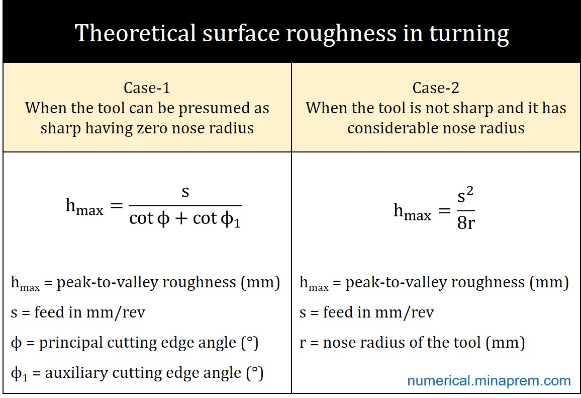
The lay marks that are generated owing to the continuous feed of the cutting tool determine theoretical surface roughness of the machined components. In the case of turning, the maximum theoretical surface roughness (peak-to-valley roughness) depends on nose radius of the tool, and accordingly it can have two different scenarios – (i) the tool is sharp having negligible nose radius, and (ii) the tool has sufficient nose radius.
Step-1: Identify the formula to be used
For a sharp tool (negligible nose radius), the maximum theoretical surface roughness (hmax in mm) can be estimated from the feed (s in mm/rev), principal cutting edge angle (ϕ) and auxiliary cutting edge angle (ϕ1), as shown below. The derivation of the formula can be found here.
\[{h_{\max }} = \frac{s}{{\cot \phi + \cot {\phi _1}}}\]
Although the tool condition (i.e. sharpness) is not explicitly mentioned in the question, the tool can be considered as a sharp one as the cutting edge angles are mentioned rather than the nose radius. So the formula corresponding to the sharp tool can be used for further calculation.

Step-2: Calculate feed rate of the tool when maximum surface roughness is 0.20 mm
The intended maximum surface roughness is provided, whereas the feed is required to calculate. It can be easily calculated from the above formula using the given values. The given values in the question and further calculation are shown below.
Maximum surface roughness (hmax) = 0.20 mm
Principal cutting edge angle (ϕ) = 90°
Auxiliary cutting edge angle (ϕ1) = 20°
\[\begin{array}{l}
{h_{\max }} = \frac{s}{{\cot \phi + \cot {\phi _1}}}\\
0.20 = \frac{s}{{\cot 90 + \cot 20}}\\
0.20 = \frac{s}{{0 + 2.75}}\\
s = 0.55
\end{array}\]
Therefore, the turning operation was carried out at 0.55 mm/rev feed.
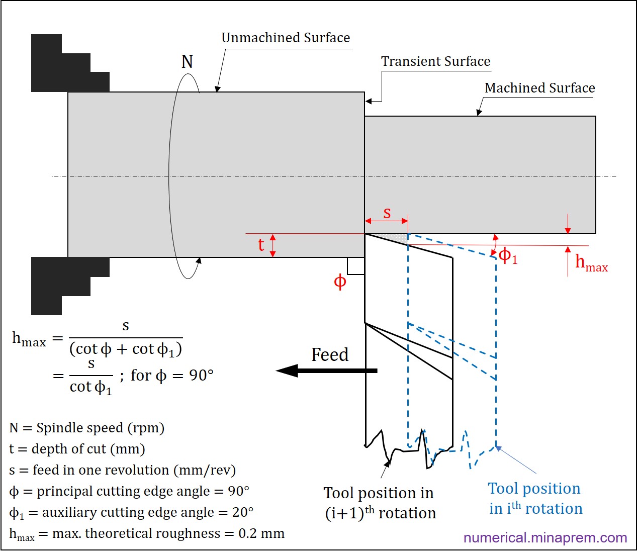
The lay marks generation during turning for the given scenario can be visualized in the following schematic. Note that the principal cutting edge angle is 90°, and the spindle speed (N) and the depth of cut (t) has no role in determining theoretical roughness height.
