Straight turning operation is carried out to reduce the diameter of a cylindrical workpiece. It is carried out in lathe with the help of a single point turning tool. The tool and workpiece are mounted firmly on the machine. The workpiece is rotated at certain speed about the machine longitudinal axis (spindle axis). The tool is also fed parallel to the machine longitudinal axis after giving the depth of cut. Presence of relative velocity between the tool and workpiece helps removing material in the form of chip.
Continuous tool feed along with the workpiece rotation leaves behind a trail of lay marks (spiral in shape) on the finished surface of the cylindrical workpiece. Such lay marks actually indicate uncut material (the material that is not removed even after completion of machining). This lay mark is the primary source of surface roughness on the turned component. It is inherent to every turning operation. The theoretical height, width and profile at any cross-section of the spiral lay mark depend on the cutting edge angles, nose radius, feed per revolution, and depth of cut.
From the tool features and process parameters, it is feasible to assess the theoretical peak-to-valley roughness of the turned component. Two different scenarios arise for such estimation – (i) when the tool is sharp, that means nose radius of the tool is negligible, and (ii) when tool is not very sharp i.e. nose radius is considerable. The procedure for deriving formulas for theoretical surface roughness in both the cases are separately discussed in the following passages. However, the following crucial points must be noted down.
- The peak-to-valley surface roughness (which is also known as maximum surface roughness) is only estimated here.
- Only the theoretical surface roughness value is estimated. The actual roughness of the turned object, if measured, can be found substantially different from this theoretical value.
- The maximum value of theoretical peak-to-valley roughness is limited by the depth of cut employed during turning.
Formula for surface roughness in turning for sharp tool


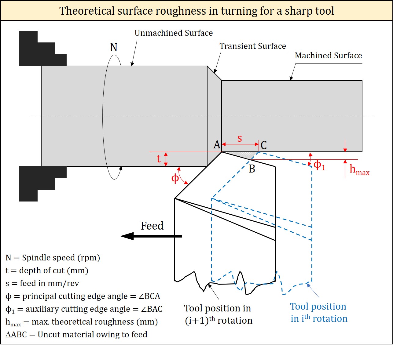
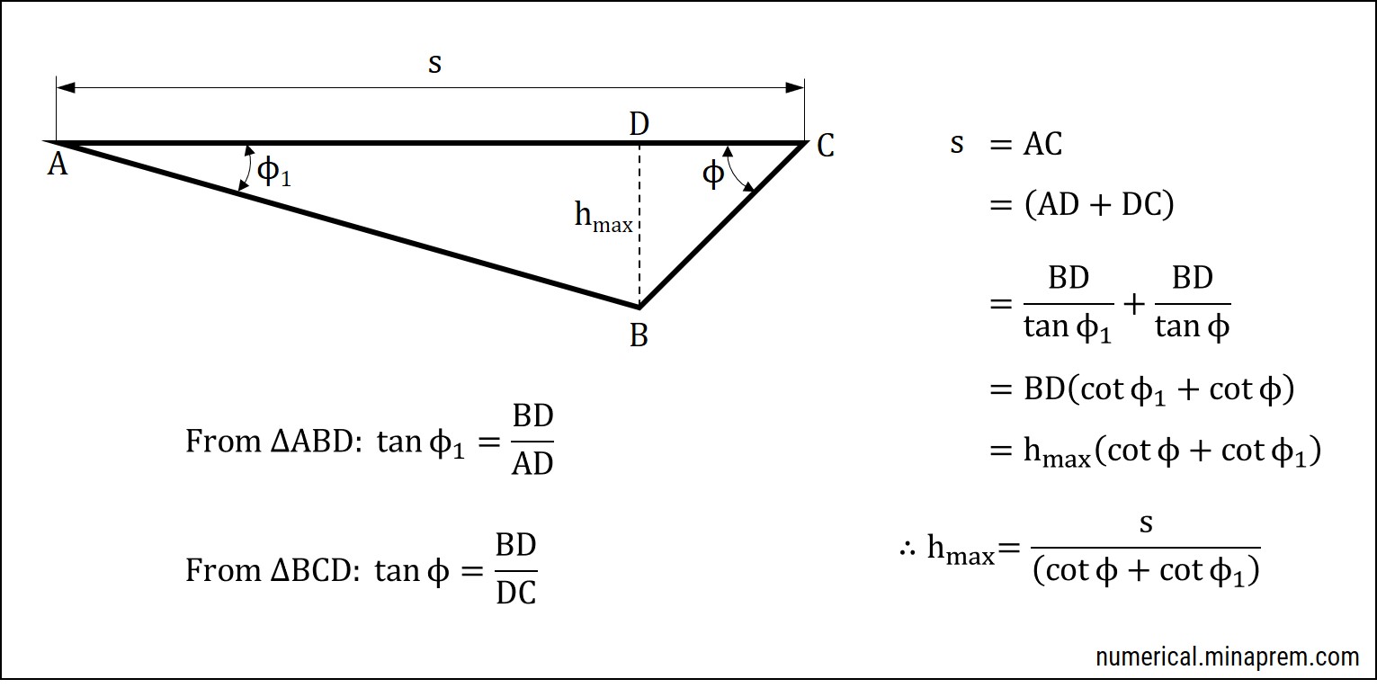
Lay marks generation during straight turning with a sharp tool is schematically shown above. Here the effect of nose radius on theoretical surface roughness is negligible. In this situation, the feed per revolution (s), principal cutting edge angle (ϕ) and auxiliary cutting edge angle (ϕ1) play crucial role in determining the height of the lay marks. Relevant derivation of formula for theoretical surface roughness is also shown above. The theoretical peak-to-valley surface roughness in this condition can be expressed as follows.
\[{h_{\max }} = \frac{s}{{\cot \phi + \cot {\phi _1}}}\]
Formula for surface roughness in turning for tool having nose radius


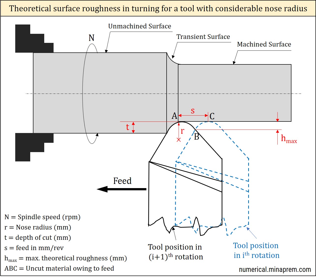
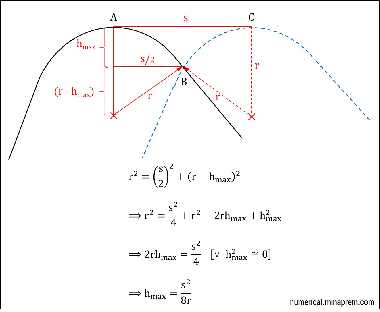
Lay marks generation during straight turning with a tool having sufficient nose radius is schematically shown above. Here the effect of nose radius on theoretical surface roughness is considerable. Note that the nose radius is different from edge radius. In this particular situation, the feed per revolution (s) and nose radius (r) play crucial role in determining the height of the lay marks. However, principal cutting edge angle (ϕ) and auxiliary cutting edge angle (ϕ1) have no direct role in this scenario. Relevant derivation of formula for theoretical surface roughness is also shown above. The theoretical peak-to-valley surface roughness in this condition can be expressed as follows.
\[{h_{\max }} \cong \frac{{{s^2}}}{{8r}}\]