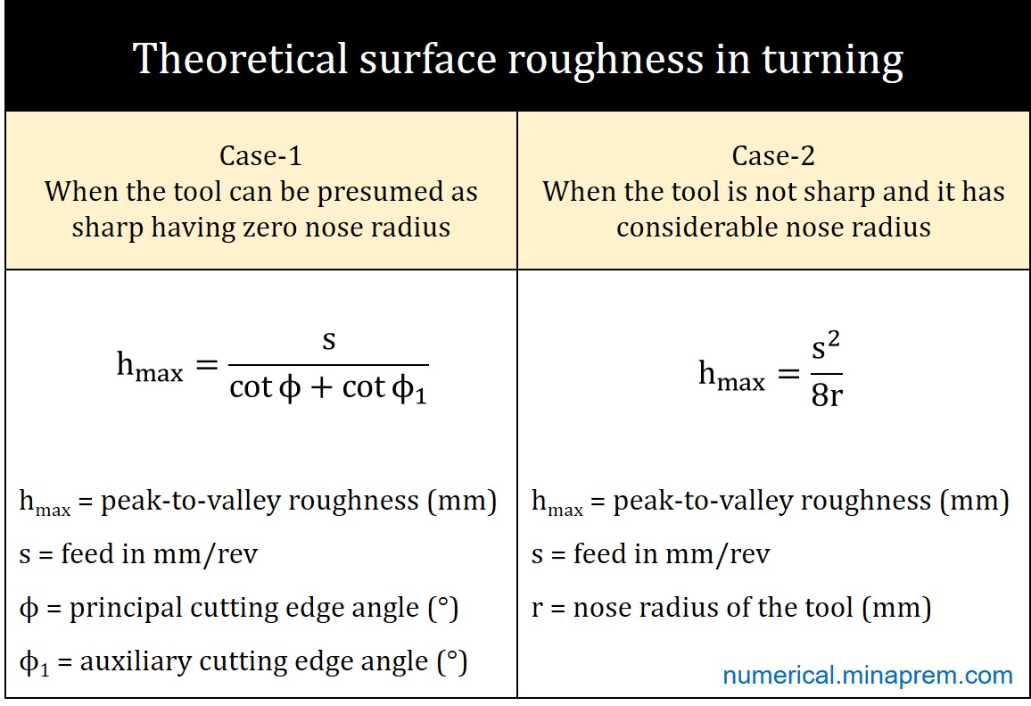
Conventional machining processes inherently generate lay marks owing to the continuous feed of the tool. This feed marks primarily determine the theoretical surface roughness of the machined component. Various tool features (such as angles and radius) also influence the theoretical surface roughness value. So far as turning operation on a lathe using a single point turning tool is concerned, the theoretical surface roughness has two distinct formulas – (i) for a sharp tool having negligible nose radius, and (ii) for a tool having considerable nose radius. Both the formulas with the derivation can be found here.
Step-1: Determine percentage change in surface roughness
In the question it is clearly stated that the tool is sharp, which indicates that the nose radius is negligible. For a sharp tool, the theoretical peak-to-valley surface roughness (hmax measured in mm) in turning can be expressed by the following formula. Here, s indicates tool feed in mm/rev, ϕ is the principal cutting edge angle, and ϕ1 is the auxiliary cutting edge angle.
\[{h_{\max }} = \frac{s}{{\cot \phi + \cot {\phi _1}}}\]
It is clearly visible from the above equation that the theoretical peak-to-valley surface roughness (hmax) does not directly depend on the depth of cut. The feed and tool angles are also independent parameters, and do not rely on the depth of cut. Therefore, variation in depth of cut does not alter the theoretical peak-to-valley surface roughness (hmax) value in turning.
Accordingly, there will be no change (i.e. 0% change) in theoretical peak-to-valley surface roughness of the turned component if only the depth of cut is changed from 2.0 mm to 2.5 mm.
